Note: A print version of The SkyComm Integrated Console System Overview can be viewed here (opens in a new browser tab).
SkyComm provides console systems that can integrate both radio and telephone channels. These systems are based on a Radio over Internet Protocol architecture (RoIP, a subset of VoIP) and are provided in two main configurations that are illustrated in the figures below:
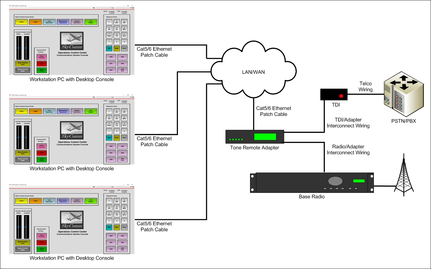
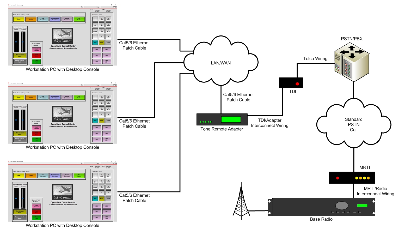
This diagram presents a console system configured for use in an airport or other fixed location. System resources (operator console positions and channels using either radio or telephone) communicate by RoIP packets transmitted over the campus or facility LAN/WAN. Conversion between RoIP packets and conventional voice and control signals occurs within the Tone Remote Adapter. A telephone resource requires an additional Telephone Dispatch Interface adapter (TDI) to facilitate connection between the telephone line from the PSTN or PBX and the Tone Remote Adapter.
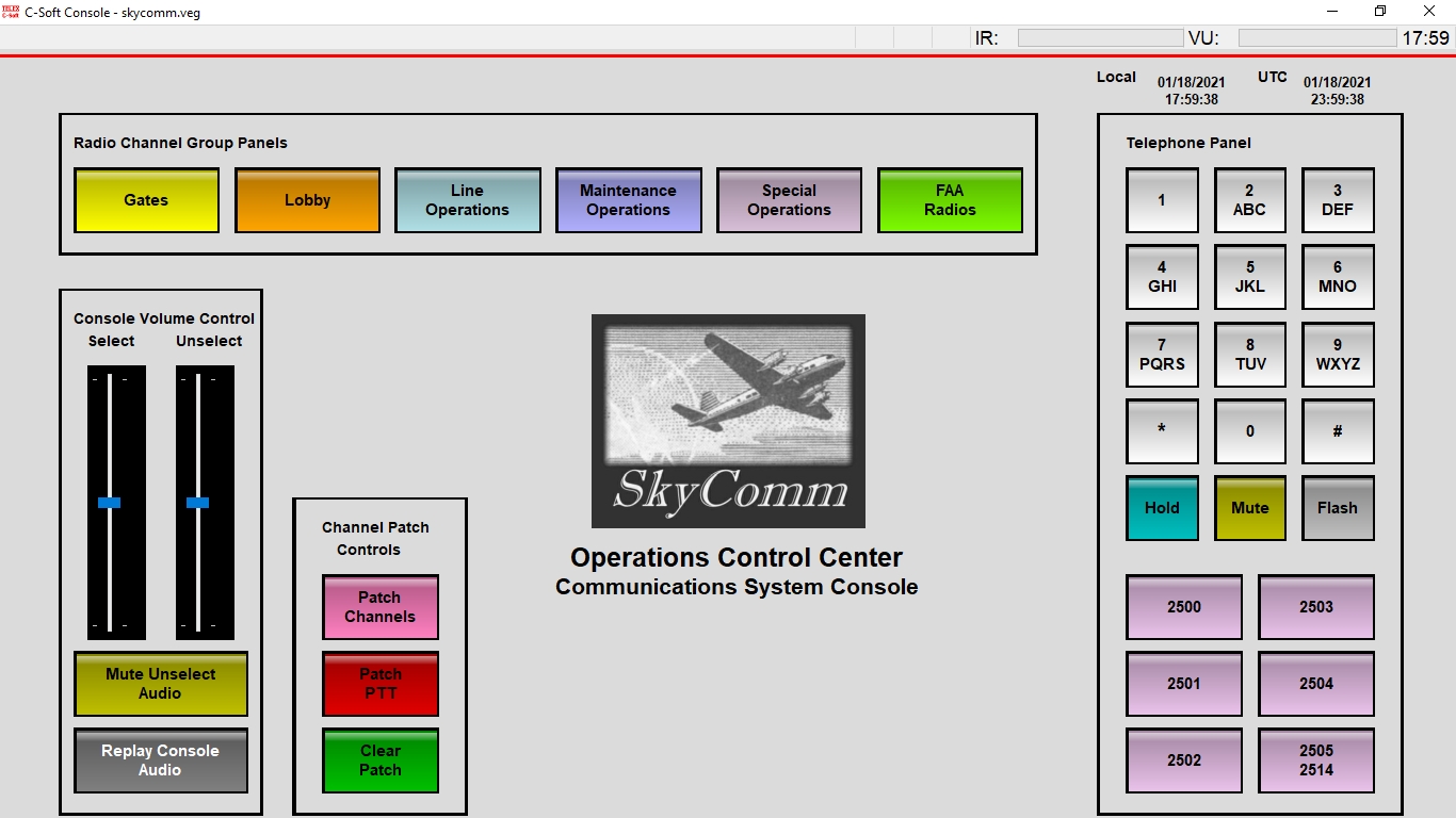
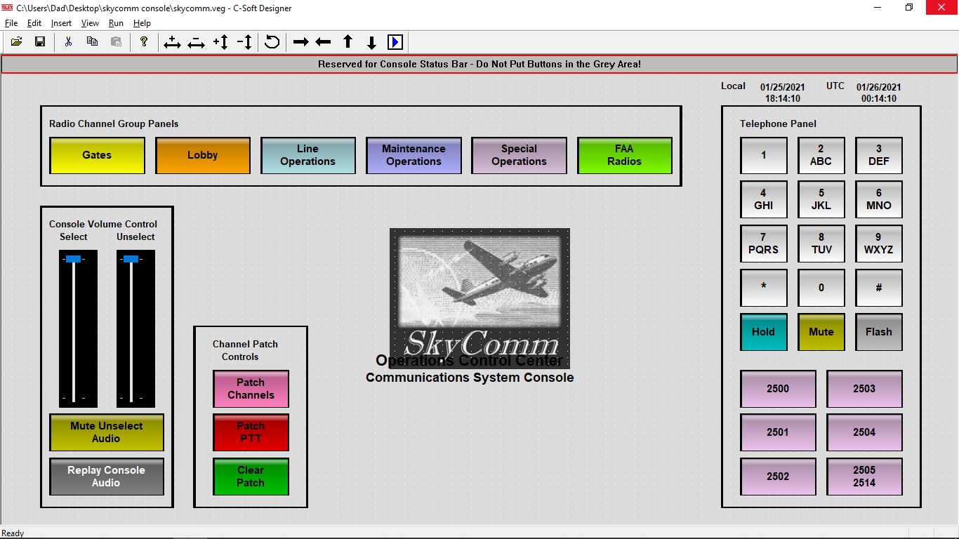
This view shows the home window for a fixed-location console position. The control buttons are sized for easy operation from a touch screen, as well as by a mouse pointer. The system's radio channels are located on separate pop-up windows that are grouped according to operational functions. These windows are displayed by selecting one or more Radio Channel Group Panels buttons. The Telephone Panel displays a telephone DTMF dialpad, HOLD, MUTE, and FLASH function buttons, and channel buttons for the system's telephone lines. The Channel Patch Group provides functionality for connecting multiple channels together ('channel patching'). The Console Volume Control provides separate master volume controls for the console's Select and Unselect receive audio streams, a mute function for all Unselect audio, and a window button to display controls for replaying console audio. VU meters for console audio are displayed in the upper right corner of the window, above the Local and UTC date/time displays.
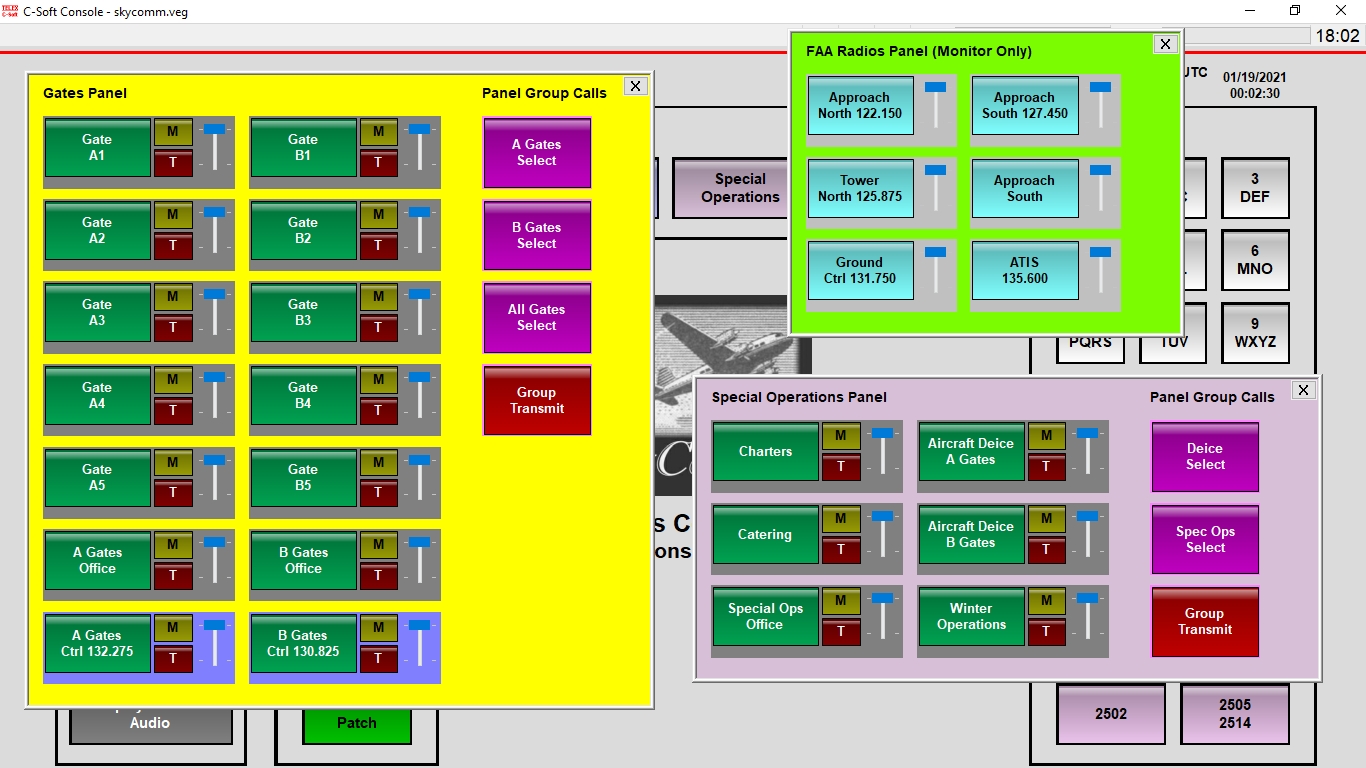
This view shows the console displaying multiple radio channel pop-up windows (Panel). Each channel control group contains the following buttons: selection (green), mute (amber), and transmit (red). Each group also contains a volume control (blue) and a VU meter (the horizontal gray area at the bottom of the group). Each window also contains Group Call controls for the selection of multiple channel receive audio (purple) and simultaneous transmission to the selected group channels (red). Note that the FAA radio channels are configured to only receive audio.
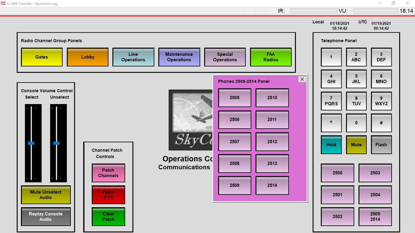
The console Telephone Panel contains a channel button labeled '2505-2514'. Selecting this button opens a window displaying an additional ten telephone lines (secondary lines) that are available to the console system.
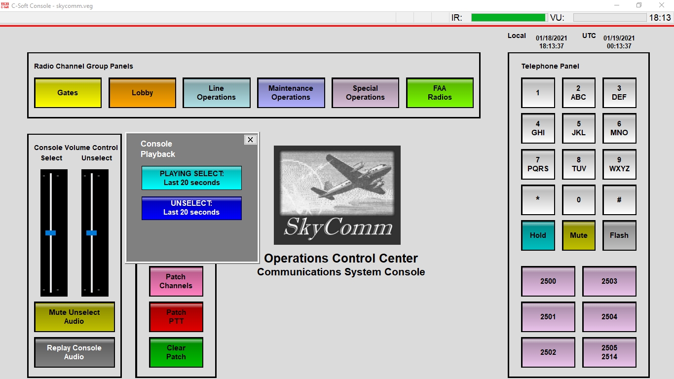
The console system has the capability of recording console audio for playback. This console system is configured to allow the operator to play back the last twenty seconds of either Select or Unselect audio. This feature is available by selecting the Replay Console Audio button. This opens the Console Playback window containing the applicable controls.
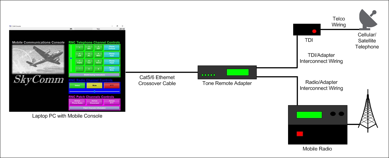
The mobile console system is designed to allow the deployment of self-contained console system to a remote location for managing an incident response or controlling an irregular operations situation. A mobile equipment rack holds the system resources. A laptop PC communicates with the Tone Remote Adapter by a Cat5/6 crossover cable, replacing the need for a LAN/WAN. Instead of connecting to a PSTN or PBX line, the TDI uses either a cellular telephone to landline adapter or a satellite telephone unit for a telephone signal.
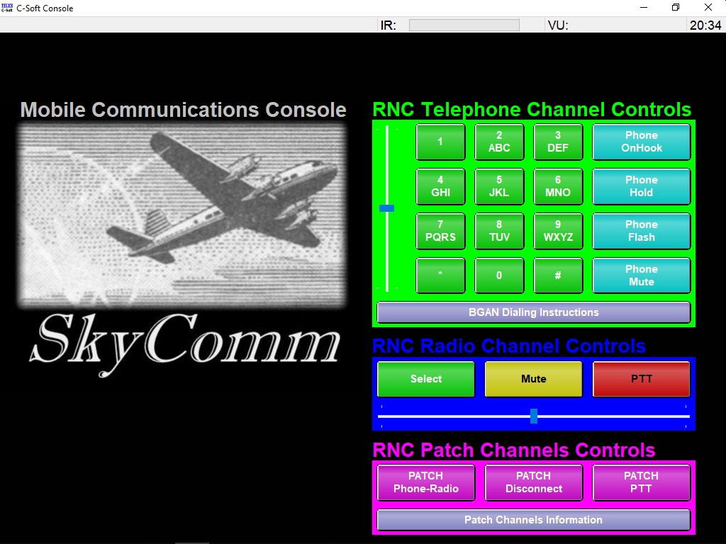
This view shows the home window for a mobile console position. This console provides controls for one telephone channel, one radio channel, and channel patching capabilities. All controls are located on this home screen, grouped by resource or operation. These controls function in the same manner as the fixed-location console. As with the fixed-location console, the control buttons are sized for easy operation from a touch screen, as well as by a mouse pointer.
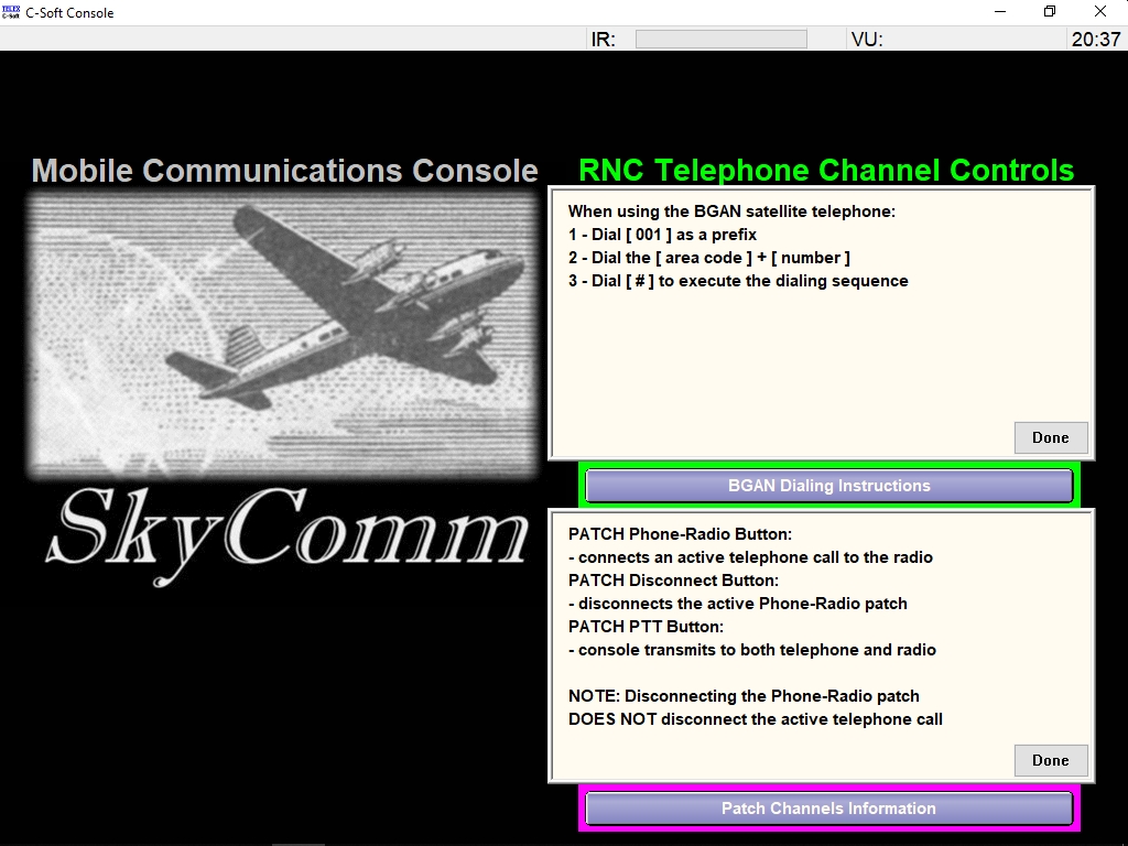
The mobile console has two control buttons that open pop-up information windows. These windows provide basic instructions for operations that, given the irregular nature of a mobile system deployment, may not be frequently performed by a console operator.
The view shows the configuration file for a fixed-location console open in the console designer application window. All of the operations for creating, configuring, or modifying a console system user interface file are performed in this application. All design features in the application are available from the main menu bar displayed in the upper left corner of the window, or from contextual pop-up menus displayed by a right-hand mouse button click on a particular control or area.
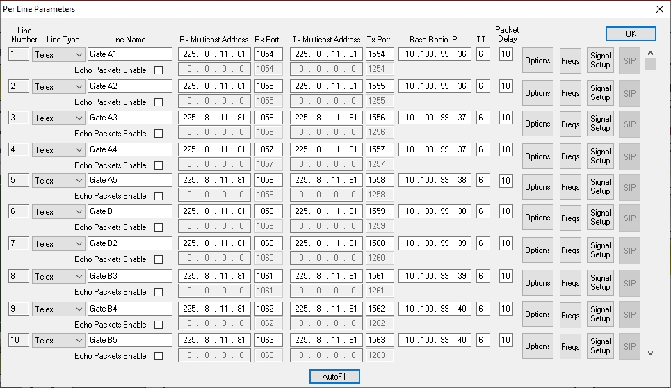
The view displays the pop-up window used for configuring the channel resources available within the console system. The RoIP parameters for the network, as well as settings for other features or options, are performed in this configuration window. Additional windows for other system configuration settings are available from the Edit menu in the designer application window.
Situations occur where a console system requires interconnectivity to a remotely-located base radio that is not connected to the LAN/WAN. This connection can be achieved by incorporating a Mobile Radio Telephone Interconnect device (MRTI) in the system. The MRTI connects the base radio to a local PSTN circuit assigned with a standard telephone number. A console operator uses an available telephone channel to call the MRTI, which then connects the base radio to the console system. The MRTI can also be configured to initiate an outbound telephone call to a console system telephone channel. This call will appear on system consoles like a standard inbound telephone call.